Cisco Troubleshooting – One Way Audio Issue

Hey everyone,

Today I’m going to talk about a common issue that I believe you’ve already faced in your infrastructure.
One way audio happens when you have a call between 2 phones (internal-internal or internal-external), and one of them cannot hear the other end.

The causes of one-way audio in IP Telephony can be varied, but the root of the problem usually involves IP routing issues.

Possible causes for the one-way audio issue:

* RTP traffic is being blocked or consumed by a Firewall or another security device.
* RTP traffic is being misrouted by a route recently added / learned, or a VRF or WAN.
* Signalling issues – Call agent is not passing the correct ports or codec, or the communication is tagged as ‘send only’ or ‘receive only’.
* RTP traffic is corrupted.
* One side is not transmitting.

A quick way to check if there’s been audio during a call is by checking its statistics.
There are 2 ways to do that. Using Jabber/Deskphones statistics, or accessing Phone’s web page and checking also the statistics.

During a call, in your Jabber, press Crtl + Shift + S to open the call statistics. A pop up window like that will appear:

image

If you are not part of the call, you can check that through phone’s web page. Open it (using phone’s IP Address), and go to Stream 1 in the left menu. The whole statistic will come up in the middle. Check if the IP address and port match the information on both sides. Keep pressing the ‘stream 1’ link and you will notice that the TX and RX stats keep increasing.
Here you can check the ‘Local’ and ‘Remote’ IP addresses, then you see the port. If the information is the same on the other side, (‘Local’ on one side should correspond to the ‘Remote’ on the other), then signalling is good.
You can also check if the Coded used is the one you were expecting.  If not, change the codec preference list or the available BW on the region.

image

Now, let’s have a  look at some scenarios and solutions, and most common issues found in the field.

  • Ensure That IP Routing Is Enabled on the Cisco IOS Gateway and Routers

Some Cisco IOS gateways, such as the VG200, disable IP routing by default. This default setting leads to one-way voice problems.
Ensure that IP routing is enabled on your router. In order to enable IP routing, issue this global configuration command on your Cisco IOS gateway:
voice-ios-gwy(config)#ip routing

  • Check Basic IP Reachability

Always check basic IP reachability first. Because Real-Time Transport Protocol (RTP) streams are connectionless (transported over UDP), traffic may travel successfully in one direction but get lost in the opposite direction. This diagram shows a scenario in which this can happen:

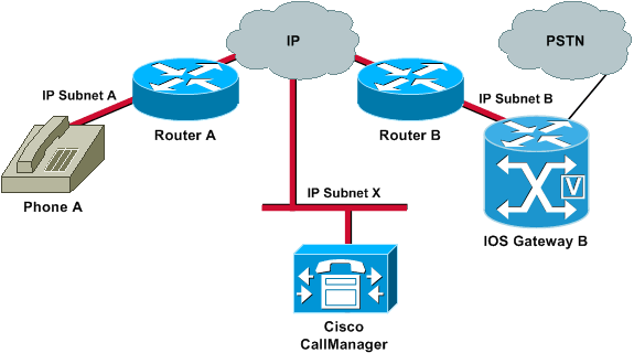
Subnets A and B can both reach Subnet X. Subnet X can reach Subnets A and B. This allows the establishment of TCP connections between the end stations (A and B) and the Cisco Call Manager. Therefore, signalling can reach both end stations without any problems, which allows the establishment of calls between A and B.

Once a call is established, an RTP stream that carries the audio must flow in both directions between the end stations. In some cases, Subnet B can reach Subnet A, but Subnet A cannot reach Subnet B. Therefore, the audio stream from A to B always gets lost.

This is a basic routing issue. Use IP routing troubleshooting methods in order to get to the stage at which you can successfully ping Phone A from Gateway B. Remember that ping is a bidirectional verification.

If transcoding is configured for an Intercluster trunk (ICT), ensure that a Media Termination Point (MTP) is configured in the Media Resource Group and Media Resource Group List associated with the trunk. If you specify an MTP when one is not needed, or fail to configure an MTP if it is needed, it has been known to cause one way voice issues for ICT configurations.

When the Cisco IOS gateway has multiple active IP interfaces, some of the H.323 signalling may be sourced from one IP address and other parts of it may reference a different source address. This can generate various kinds of problems. One such problem is one-way audio.

In order to get around this problem, you can bind the H.323 signalling to a specific source address. The source address can belong to a physical or virtual interface (loopback). Use the h323-gateway voip bind srcaddr ip-address command in interface configuration mode. Configure this command under the interface with the IP address to which the Cisco Call Manager points.

One-way voice can occur in Media Gateway Control Protocol (MGCP) gateways if the source interface for signalling and media packets is not specified. You can bind the MGCP media to the source interface if you issue the mgcp bind media source-interface interface-id command and then the mgcp bind control source-interface interface-id command. Reset the MGCP gateway in Cisco Call Manager after you issue the commands.

If the mgcp bind command is not enabled, the IP layer still provides the best local address.

The guidelines for the mgcp bind command are:

*   When there are active MGCP calls on the gateway, the mgcp bind command is rejected for both control and media.
*   If the bind interface is not up, the command is accepted but does not take effect until the interface comes up.
*   If the IP address is not assigned on the bind interface, the mgcp bind command is accepted but takes effect only after a valid IP address is assigned. During this time, if MGCP calls are up, the mgcp bind command is rejected.
*   When the bound interface goes down, either because of a manual shutdown on the interface or because of operational failure, the bind activity is disabled on that interface.
*   When bind is not configured on the Media Gateway Controller (MGC), the IP address that is used to source MGCP control and media is the best available IP address.

If you find that there are clock slips on the E1 or T1 interface from the show controller {e1 | t1} command, there might be some mismatch in the clocking configuration on the Voice Gateway.

Two useful commands to use in order to verify packet flow are the debug cch323 rtp command and the debug voip rtp command. The debug cch323 rtp command displays packets that are transmitted (X) and received (R) by the router. An uppercase character indicates successful transmission or reception. A lowercase character indicates a dropped packet.

voice-ios-gwy#debug cch323 rtp

RTP packet tracing is enabled
voice-ios-gwy#

!— This is an unanswered outgoing call. !— Notice that the voice path only cuts through in the forward direction and !— that packets are dropped. Indeed, received packets are traffic from the !— IP phone to the PSTN phone. These are dropped until the call is answered.

Mar 3 23:46:23.690: ****** cut through in FORWARD direction *****

XXXrXrXrXrXrXrXrXrXrXrXrXrXrXrXrXrXrXrXrXrXrXrXrXrXrXrXrXrXrXrXrXrXrXrXrXrXrXrXrXr
XrXrXrXrXrXrXrXrXrXrXrXrXrXrXrXrXrXrXrXrXrXrXrXrXrXrXrXrXrXrXrXrXrXrXrXrXrXrXrXrXr
XrXrXXrrrrrrrrrrrrrrrr
voice-ios-gwy#
voice-ios-gwy#

!— This is an example of an answered call:


voice-ios-gwy#
voice-ios-gwy#
*Mar 3 23:53:26.570: ****** cut through in FORWARD direction *****
XXXrXrXrXrXrXrXrXrXrXrXrXrXrXrXrXrXrXrXrXrXrXrXrXrXrXrXrXrXrXrXrXrXrXrXrXrXrXrXrXr
XrXrXrXrXrXrXrXrXrXrXrXrXrXrXrXrXrXrXrXrXrXrXrXrXrXrXrXrXrXrXrXrXrXrXrXrXrXrXrXrXr
XXrrrrrXrXrXrXrXrXrXrXrXrXrXrXrrXXrrXrXrXrXrXrXXXXXXXXXXXXXXXXrXXXXXXXXrXrXrXXrrXr
XrXrXrXrXrXrXrXrXXrrrrrrrrrrrrrrrrrrrrrrrrrrrrrr

!— At this point, the remote end picks up the phone.


*Mar 3 23:53:30.378: ****** cut through in BOTH direction *****
XRXRXRXRXRXRXRXRXXRRRRRRRRRRRRRRRRRRRRRRRRRRRRRRRRRRRRRRRRRRRRRRRRRRXRXRXRXRXRXRXR
XRXRXRXRXRXRXRXRXRXRXRXRXRXRXXRRRRRRRRRRRRRRRRRRRRRRRRRRRRRRRRRRRRRRRRRRXRXRXRXRXR
XXRRXRXRXXRRXRXRXRXRXXRXRXRXRXRXRRXRXXRXRXRXRXRXRXRXRXRXRXRXRXRXRXRXRXRXRXRXRXRXR
XRXRXRXRXRXRXRXRXRXRXRXRXRXRXRRRRRRRRRRRRRRRRRRRRXRXRXRXRXRXRXRXRXRXRXRXRXRXRXRXR
XRXRXRXRXRXRXRXRXRXRXRXRXRXRXRXXRRRRRRRRRRRRRRRRRRRRRRRRRRRRXRXRXRXRXRXRXRXRXRXR
XRXRXRXRXRXRXRXRXRXRXRXRXRXRXRXRRRRRRRRRRRRRRRRRRRRRRRRRRRRRRRRRRRRRRRRRRRRRRRRRRRRR
RRRRXRXRXRXRXRXRXRXRXRXRXRXRXRXRXRXRXRXRXRXRXRXRXRXRRXXRXRXRXRXRXRRXRXRXRXRXRXRXRXR
XRXRXRXRXRXRXRXRXRXRXRXRXRXRXRXRXRXRXXRRRRXRXRXRXRXRXRXRXRXRXRXRXRXRXRXRXRXRXR
XXRRRRRRRRRXRXRXRXRXRXRXRXRXRXRXRXRXRXRXRXRXRXRXRXRXRXRXRXRXRXRXRXRXRXRXRXRXRXRXRXR
XRXRXRXRXRXRXRXRXRXRXRXRXRXRXRXRXRXRXRXRXRXRXRXRXRXRXRXRXRXRXRXRXRXRXRXRXRXRXRXRXR
XRXRXRXRXRXRXRXRXRXRXRXRXXRRRXR

!— This is the end of the conversation.

Note: In Cisco IOS Software Release 12.2(11)T and later, the debug cch323 rtp command-line interface (CLI) command has been replaced by the debug voip rtp command.

voice-ios-gwy#debug voip rtp

——–cut through in BOTH direction——————-


*Mar 27 19:52:08.259: RTP(32886): fs rx d=10.48.79.181(20002),
pt=0, ts=4FFBF0, ssrc=8E5FC294
*Mar 27 19:52:08.275: RTP(247): fs tx d=10.48.79.181(20002),
pt=0, ts=5D00C8D9, ssrc=1F1E5093
*Mar 27 19:52:08.279: RTP(32887): fs rx d=10.48.79.181(20002),
pt=0, ts=4FFC90, ssrc=8E5FC294
*Mar 27 19:52:08.295: RTP(248): fs tx d=10.48.79.181(20002),
pt=0, ts=5D00C979, ssrc=1F1E5093
*Mar 27 19:52:08.299: RTP(32888): fs rx d=10.48.79.181(20002),
pt=0, ts=4FFD30, ssrc=8E5FC294
*Mar 27 19:52:08.315: RTP(249): fs tx d=10.48.79.181(20002),
pt=0, ts=5D00CA19, ssrc=1F1E5093
*Mar 27 19:52:08.319: RTP(32889): fs rx d=10.48.79.181(20002),
pt=0, ts=4FFDD0, ssrc=8E5FC294
*Mar 27 19:52:08.335: RTP(250): fs tx d=10.48.79.181(20002),
pt=0, ts=5D00CAB9, ssrc=1F1E5093
*Mar 27 19:52:08.339: RTP(32890): fs rx d=10.48.79.181(20002),
pt=0, ts=4FFE70, ssrc=8E5FC294
*Mar 27 19:52:08.355: RTP(251): fs tx d=10.48.79.181(20002),
pt=0, ts=5D00CB59, ssrc=1F1E5093
*Mar 27 19:52:08.359: RTP(32891): fs rx d=10.48.79.181(20002),
pt=0, ts=4FFF10, ssrc=8E5FC294
*Mar 27 19:52:08.375: RTP(252): fs tx d=10.48.79.181(20002),
pt=0, ts=5D00CBF9, ssrc=1F1E5093
*Mar 27 19:52:08.379: RTP(32892): fs rx d=10.48.79.181(20002),
pt=0, ts=4FFFB0, ssrc=8E5FC294
*Mar 27 19:52:08.395: RTP(253): fs tx d=10.48.79.181(20002),
pt=0, ts=5D00CC99, ssrc=1F1E5093
*Mar 27 19:52:08.399: RTP(32893): fs rx d=10.48.79.181(20002),
pt=0, ts=500050, ssrc=8E5FC294
*Mar 27 19:52:08.976: RTP(282): fs tx d=10.48.79.181(20002),
pt=0, ts=5D00DEB9, ssrc=1F1E5093
*Mar 27 19:52:08.980: RTP(32922): fs rx d=10.48.79.181(20002),
pt=0, ts=501270, ssrc=8E5FC294
*Mar 27 19:52:08.996: RTP(283): fs tx d=10.48.79.181(20002),
pt=0, ts=5D00DF59, ssrc=1F1E5093

*Mar 27 19:52:09.000: RTP(32923): fs rx d=10.48.79.181(20002),
pt=0, ts=501310, ssrc=8E5FC294
*Mar 27 19:52:09.016: RTP(284): fs tx d=10.48.79.181(20002),
pt=0, ts=5D00DFF9, ssrc=1F1E5093

This is all for today.

I hope you’ve enjoyed Smile

See ya!

Bruno

Cisco Finesse – Adding 3rd Party Gadgets

Hey guys,

In this post, I’m going to show you how to add new gadgets to your Cisco Finesse.
It can be any special gadget you may have created, or even a simple web page to be opened in one of the Finesse Tabs.

Finesse itself allow you to upload third-party gadgets. It’s done via an specific user, 3rdpartygadget. This account only has permission to this directory, /files, and any directories created under it.

  • Set a Third Party Gadget account password

To start off, we need firstly to set a password for this account, via CLI.
So, connect via SSH into your UCCX server and enter the line command: utils reset_3rdpartygadget_password .
For the password, enter ciscocisco,  and confirm it.

image

Not, it’s time to upload your Gadget to the server.
Finesse gadgets are OpenSocial gadgets. An OpenSocial Gadget is an XML document that defines metadata for an OpenSocial Gadget container, the Finesse agent desktop. Gadgets are highly cacheable so it does not need a high-performance server.

A gadget consists of the following:

  • XML to define metadata
  • HTML for markup
  • JavaScript for interactivity
  • CSS for presentation & style

Let’s see now the steps to upload your files. For this task, I’m using FileZilla (download):

  1. Open FileZilla.
  2. In the quickconnect bar,
    in red, fill the following fields:
  • Enter the Finesse FQDN: {{web-url}} in the Host field.
  • Enter 3rdpartygadget in the Username field.
  • Enter ciscocisco in the Password field. This is the 3rdpartygadget password defined in the previous step.
  • Enter 22 in the Port field.
  • Click Quickconnect.

image

  • If a message pops up, about Unknown host key, select Always trust this host, add this key to the cache, and then OK.
  • You must see now a message like that in the log section: Status:     Connected to <URL>.
  • In the remote site section, confirm that you see a folder named / and you can see the files folder below.

image

Now you have to transfer your Gadgets file to the server:

  • Drag the EmbeddedWebApp folder (that contains the xml, js, and css) into the files folder. Note that this is the folder inside of the EmbeddedWebAppSampleGadget-Finesse-x.x.x-vx.x folder.
  • Confirm that the transfer was successful by checking that the transfers shows up in the Successful transfers tab at the bottom.

image

Give the right permission to the files. They have to have public read permission to be loaded o the Finesse Agent Desktop.

  • Select the EmbeddedWebApp folder.
  • Right-click on the EmbeddedWebApp folder.
  • From the dropdown menu, select File permissions….
  • A Change file attributes window appears.
  • Under Public permissions verify that Read permissions is selected.
  • Select Recurse into subdirectories.
  • Click OK.

image

In my case, I’ve added a new Tab to my Finesse, and added my gadget. This gadget opens a URL in my webserver, an it’s used only by Supervisors.

To do that, go to your UCCX, then go to Cisco Finesse Administrator

image

Go to Team Resources, and select the Team you want to change the Layout to include your new Tab/Gadget:

image

In the box below, you see now the Desktop Layout Configuration.
This is how your Finesse will look like, and its gadgets.
First thing you have to do, is to select the option Override System Default. So you can edit the XML.

image

So now, you have to copy all that XML file to a notepad, and add manually the Tab you want to have, and the gadget you just have added.
In my case, I want only Supervisors to have access to it, so in the XML, I go direct to the second block, which is related to Supervisors.

My XML will be like that:

I’ve added 2 Tabs: one called ISR Management, and a second one, TEST

image

After adding the new Tab to your XML, you have to Copy and Paste it back to your Desktop Layout Configuration, and Save it.

Now go back to your Finesse, and you must be able to see the 2 Tabs you just added:

image

In my case, when I select the Tab, it runs a page from my webserver:

image

I hope you like it Smile

See ya!

Bruno

Cisco CUCM – Intercluster Lookup Service

Hey people,

Today I’m going to explain the concept of a good feature, called ILS (Intercluster Lookup Service).
ILS enables different CUCM Cluster to exchange directory URI with other clusters in an ILS network, allowing you to create networks of remote CUCM clusters. So, when you configure ILS on multiple clusters, it updates CUCM with the current status of remote clusters in the ILS network.
An ILS network comprises the following components:

Hub Clusters
Hub clusters form the backbone of an ILS network. Hub clusters exchange ILS updates with the other hub clusters in the ILS network, and then relay that information to and from their spoke clusters.

Spoke Clusters
A spoke cluster connects to the hub cluster in an ILS network to relay ILS updates to and from the rest of the ILS network. Spoke clusters contact only their local hub cluster and never directly contact other hub clusters or other spoke clusters. A spoke cluster can have only one hub cluster.

Global Dial Plan Imported Catalogues
To provide URI dialling compatibility with third-party systems, you can manually import a third-party directory URI or +E.164 number catalog from a CSV file into any hub cluster in the ILS network

CONFIGURATION

Let’s go deep to the configuration. For that, I’m going to use this topology as example:
2 CUCM clusters in the ILS network.

  • 10.106.79.71 – HQ Cluster
  • 10.106.79.83 – BR Cluster

topology.png

  • Activate Intercluster Lookup Service on all the CUCM Publisher

    You must activate the Intercluster Lookup Service to configure Cluster IDs and Remote Clusters.
    From Cisco Unified Serviceability, choose Tools > Service Activation.
    From the Server drop-down list, choose the node and then click Go.
    Select ‘Intercluster Lookup Service’ and Save.

    0.png

  • Configure Cluster IDs

    You must configure a unique cluster ID for each cluster in the ILS network. The clusters use this unique cluster ID and peer ID when they exchange status messages.
    In Cisco Unified Communications Manager Administration, choose System > Enterprise Parameters.
    In the Enterprise Parameters Configuration window Cluster ID field, enter a name of the cluster that you
    want to configure in your network.

    1.png

  • Activate ILS on the Hub Cluster

    You must configure each cluster in your ILS network as either a hub cluster or a spoke cluster. Each ILS network must have at least one hub cluster. You can connect a hub cluster to other hub clusters, or you can configure a hub cluster as the only hub cluster in the network. In addition, you can connect a hub cluster to multiple spoke clusters, or you can configure the hub cluster with no spoke clusters.

    Now, considering the Node 10.102.79.71 as the ILS HUB Cluster.

    Go to Advanced Features > ILS Configuration > and configure as follows.

    AA1.png

    Route String: This will be a unique string that will be advertised to the other clusters. Other ILS peers use Route String to route the call.

    Above configuration uses ‘Password’ based ILS authentication and synchronize the clusters every 1 minute.
    The moment you click Save, it will ask for ILS Registrar Server. Since I do not have any other HUB cluster, we can leave blank and click OK.

    4.png

  • Activate ILS on the Spoke Cluster

    Now, the node 10.106.79.83 will be  the SPOKE cluster.
    Go to Advanced Features > ILS Configuration > and configure as follows.

    A2.png
    When you click Save, enter the Registrar server as the HUB cluster 10.106.79.71.

    6.png


    Now refresh the ILS configuration to see the updated status.

    A3.png

  • Configuring URIs for the End Users

    Go to User Management > End User > and select the user you want to enable URI.
    For LDAP user, make sure the URI is synced from LDAP server. For the local users, you can set a URI as shown below.
    CUCM End User URI Configuration.png

    Then, go to the Controlled Devices section and assign the user’s desk phone as the controlled device. Also, configure the primary extension (mandatory!!).

    Primary extension for URI dialing.png

    Now go to the Directory number configuration(e.g. 1002). Now you will be able to see the URI field.

    Direcory URI configuration CUCM.png

  • Verify the Learned Directory URIs

    Go to Call Routing > Global Dial Plan Replication > Learned Directory URIs

    9.pngA4.png

    Any of the URI learned via ILS will be having 2 unique values. One is the Route String and another one is Cluster ID. Route String is used to route the call back to the respective cluster via a separate SIP trunk.
    ILS will only take care of advertising the URIs between clusters. They do not participate in call routing. For dialling the URI from one cluster to another, we need to have a separate SIP trunk.

  • ILS Restrictions


    imageimage

  • ILS Troubleshooting

    Here are some Troubleshooting Tips:

    Issue: Local Cluster Cannot Connect to the ILS Network

    To troubleshoot connection issues within the local cluster, open RTMT and run alarms and diagnostic traces on that publisher node. If you receive an error message when trying to establish ILS between your clusters, you can try to restart the Cisco Intercluster Lookup service from Cisco Unified Serviceability Administration. In addition, connection issues may arise if authentication is improperly configured between clusters. Check authentication in the following manner:
    • If you are using TLS, make sure that all clusters in the network are using TLSand that Tomcat certificates have been exchanged for all the servers that need to communicate.
    • If you are using TCP password authentication, make sure that all ILS clusters are using TCP password authentication and that the same TCP password is assigned across the network.

    Issue: Directory URIs Are Not Being Replicated Across the ILS Network

    This error can occur for a variety of reasons. Check the following:

    • Verify that all clusters in the network are configured to exchange global dial plan data. If a hub cluster is not configured to exchange global dial plan data, none of that hub’s spoke clusters will be able to exchange directory URI catalogs.
    • Allow enough time for end-to-end replication based on synchronization intervals (set on the ILS Configuration page) that are configured for all the clusters involved in the path. All clusters in an ILS network are a maximum of three hops from every other cluster in the network.
    • Use the utils ils showpeerinfo CLI command to monitor replication progress by looking at the USN values for the remote clusters.
    • Increase speed of replication by changing the ILS Sync Throttle Service Parameter. Note that a low setting can affect system performance.
    • Verify that all clusters in the ILS network have unique cluster IDs and that none of the clusters are configured with Stand Alone Cluster as its cluster ID. You can check Cluster IDs in Cisco Unified CM Administration under System > Enterprise Parameters.

    Issue: Global Dial Plan Replication Is Configured, but Unified CM Still Cannot Place a Call to A Learned Directory URI or Learned Number in a Remote ILS Cluster

    This condition can occur if ILS and Global Dial Plan Replication are enabled on all clusters in the network, but SIP route patterns that route to the route strings for the remote clusters have not been configured. Do the following:
    • In the ILS Clusters and Global Dial Plan Imported Catalogs view in the ILS Configuration window, check the route string for the remote cluster.
    • In the SIP Route Pattern configuration window, make sure that you have route patterns that map to the route strings for your remote clusters

    Hope you’ve enjoyed Smile

    See ya!

    Bruno

Cisco UCCX – Sending email using Script

Hi people!
In today’s post, I will show you how to configure your UCCX Script to send emails.

This can be easily a complement of my last Post (Cisco UCCX – Recording Prompt Script). In this post, I showed you how to create a script where you can record your own audio prompts and upload them to UCCX. Now, with this post, you can add some steps to send the recorded audio via email to improve a little bit your achievement.

Well, let’s go to the configuration!

Configure Email on UCCX Server
Go to your UCCX,  Subsystem Menu, then Email.
You have to add the SMTP and an email account which will be the source.

image

Variables
You can have as many variables as you want to easy your life. But there is one you must create.
Create a Contact Type variable, give a name,  “EmailContact” in my example, and give a null value.

image

Steps to be used in the Script

  • Create eMail
    Here you generate the subject line and body of the e-mail message.
  • Subject: Variable or expression that you want to use for the subject line of the message.
    Body: Variable or expression that you want to use for the body of the e-mail message
    eMail Contact: Variable that identifies the email. The variable “EmailContact”  we’ve created above.

    image

  • Attach To eMail
    Use the Attach To eMail step to attach a document to an e-mail.
    Before you use an Attach To eMail step, you must use a Create eMail step to create the e-mail message.

    I’m showing you now how to attach that audio prompt we’ve just recorded, as an example.
    In that case, the variable Result contains the recorded audio, and I’m attaching it to the email using this Step.

    image

  • Send eMail
    Use the Send eMail step to send an e-mail message you have created with the Create eMail step.
    When a script reaches the Send eMail step, it immediately sends the e-mail message to the e-mail server, and keeps the client waiting until the message is accepted by the e-mail server. If the server is unavailable because of server or network problems, the client must wait until the transaction times out.

image

So, your code must be like that.

image

It’s a really short code, but the idea is to have that attached to your main script, as a feature, to help you to handle queues, or other things, like sending recorded audios..

Hope you’ve enjoyed!
See ya!

Bruno

Cisco UCCX – Recording Prompt Script

Hey Guys,

Today I’m going to show you the step-by-step to create a Script on UCCX, where you can record your own Audio Prompt. The audio is automatically saved in a Folder on UCCX.

It’s not an advanced Script, but it’s very useful.
Audio will be saved with the User’s ID, plus the date/time. I found this way easy to be found in the Folder, for instance: 1234567_07_19 – 10018am.wav.

Let’s see the steps to create the Script:

  • Defining Date/Time
    We are going to get the current Date and Time, and then, split it into 4 variables: second, minutes, hour, month and day. Then, add then in a variable sSlotTime, which will be part of the name of the Audio.
    These steps Switch are add the “0” in a number. For example, from “1” to “01”, so we keep all with 2 digits. We do the same for day, month, hour, minutes and second (always from 0 to 9).
    For the period, the result will give us 1 or 0. If it’s 1, I set the period to pm. If it’s 0, I set the period to am.


imageimage

imageimage

  • Getting User ID
    Now we will ask the user to enter their ID’s. The only reason here is to name the audio according to the ID. If you want, you can ask the user to enter ID and PIN as an authentication.
    You are saving the ID in a variable called ID.
    Then, we are setting the variable sFileType with ID + “_”.

imageimage

image

  • Recording
    Time now to Record the audio. To do that, there is a step called Recording, where you indicate which variable you will save the result, audio, maximum duration, etc..
    So we are saving it in a variable called Result.

image
imageimageimage

  • Manipulating the Result
    After recording the audio(with success), I’m giving 3 options to the user, through a Menu:

image
Press 1 to Listen the recorded audio – The audio saved in the variable Result will be played.
Press 2 to Save – We will give a full name to the audio. Variable sFileName will receive the Folder + sFileType + sSlotTime + “.wav”
Press 3 to Record it again – Go back to the Recording Step

image

  • Authentication
    To be able to save the audio to UCCX, we need authenticate, with an admin credential.
    So firstly, we need to Get the User, then you have to authenticate it.

imageimageimage
image

  • Saving the audio
    After authenticating, we have to save the file in the audio repository.
    We use the step Upload Prompt to send the audio to the Server. If the Upload is done successfully, user will listen to a Menu, asking to press 1 to Record another audio, or any digit to finish.image
    The file name is that variable sFileName we’ve prepared, and the Document is the audio saved in the variable Result.

    image

Basically, this is the code!

YOU CAN NOW DOWNLOAD THE SCRIPT HERE!!
I hope you enjoyed!

See ya!

Bruno

imageimageimage